This post was transferred from its original home on another blog. The formatting is a mess, but maybe it can still entertain someone.
Long overdue update
During the project demo, my Senseo ruined three Arduinos, one of which over a CAN-bus connection, and a USB port. I'm moderately proud of the remotely triggered explosion, but I can't stress enough how careful you need to be.
A few weeks ago I got the idea to mod my old Senseo pod coffee machine in order to control it remotely for a college project. It's finished and done, and I'm here to tell you how. For this post, I'll limit myself mostly to the electronics - the programming is a story of its own, although it didn't take me nearly as long.
Disassembly
 Before I could tinker with the insides of my coffee machine I knew I'd have to
take it apart. "No worries," I said to my self, "I'm pretty good at taking
things apart!" I had no idea what I was getting into. I'll spare you the
gruesome details and summarize: While serviceable, it's a pretty tough
machine - halfway in I realized I didn't have quite the right maintenance
manual and couldn't get one from Philips, and I ended up breaking every single
clip that keeps the bottom in place. I got in, and that's when it got
interesting.
Before I could tinker with the insides of my coffee machine I knew I'd have to
take it apart. "No worries," I said to my self, "I'm pretty good at taking
things apart!" I had no idea what I was getting into. I'll spare you the
gruesome details and summarize: While serviceable, it's a pretty tough
machine - halfway in I realized I didn't have quite the right maintenance
manual and couldn't get one from Philips, and I ended up breaking every single
clip that keeps the bottom in place. I got in, and that's when it got
interesting.
I wrote this post as a story as well as an informal manual of how to approach this sort of project. As a result it may not do a very good job at either, but I hope it's interesting or useful to some. Feedback on my style, my methods or any bad advice I may be giving is very welcome.
Obligatory warnings and disclaimers: This will void your warranty. I will not be held responsible for any damage to devices, or for harm to yourself or others. Be respectful of electricity and it may not kill you.
Analysis
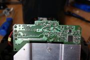
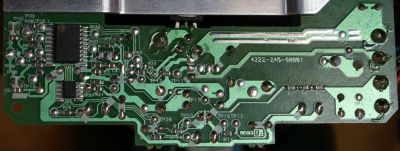 The first order of business was figuring out where everthing is on the PCB.
Even if my maintenance manual had been the right one it didn't come with any
schematics, so I had the opportunity to poke and probe my way through a live
circuit. Most of it is logic level, but a good few - unlabeled - areas were
at 230 V.
The first order of business was figuring out where everthing is on the PCB.
Even if my maintenance manual had been the right one it didn't come with any
schematics, so I had the opportunity to poke and probe my way through a live
circuit. Most of it is logic level, but a good few - unlabeled - areas were
at 230 V.
Tip
Seriously, don't mess around with this. Even before I got shocked I made sure to have an off switch near my foot and afterwards I used rubber gloves much of the time. When you bump your hand into a live mains wire you'll probably jerk away, but even then it's not fun.
Identifying the various functions wasn't terribly hard. I'd already realized that I wouldn't be interacting with the microcontroller directly - soldering is not my forte - so it was limited to pulling one side of each button low and reading sensor data.
Now to figure out what the sensor data is and where to get it. How? With science, that's how:
- Decide what you want to know. For instance, I had to know whether the water level is high enough to make a cup of coffee.
- Figure out how the machine knows about that. In the case of the water level, I know where the sensor is: it's a float switch in the rear, activated by a magnet in the water tank.
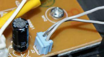 Follow wires and/or PCB traces to a place where you might get a
useful readout. Easy with this sensor - it's plugged into the mainboard as
you can see to the right, so I could just prod a probe in there.
Follow wires and/or PCB traces to a place where you might get a
useful readout. Easy with this sensor - it's plugged into the mainboard as
you can see to the right, so I could just prod a probe in there.- Think about what you expect to measure when changing the sensor's input. It's a plain on/off toggle, so my initial hunch was that I'd see low output initially, rising to high when getting near the sensor with a magnet. What I didn't know was which side of the plug would be changing.
- Find a comfortable and safe way to measure this. I'd need to ground one probe, hold the other at the plug and move a magnet near the sensor. A crocodile clip or a third hand may be helpful.
- Set your DMM to measure voltage at a sensible range. It's fairly safe to assume logic level at this point, but it won't hurt to start higher when you're not absolutely sure it's the right spot.
- Turn the machine on.
- Measure. Keep the probe in one place and toggle sensor input.
- Record your measurements. I can't stress this enough: if I hadn't diligently kept a log of everything I measured I'd have had a terrible time rechecking everything all the time.
- If necessary, move the probe to the other side and repeat steps 8 and 9.
- Turn the machine off. It's no good leaving an exposed system turned on while you're not working on it.
When all this was done I knew that pin 1 of the plug is always high, and pin 2 rises from 0 V to 0.8 V when the sensor is triggered.
Putting things together
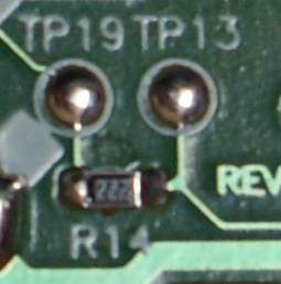 Then came the part that worried me most: I had to connect wires to everything
I wanted to interact with. I'm honestly no good at soldering, but for the
most part there was no alternative. Fortunately, these PCBs need to be tested
after production which means that often enough you'll find test pads. Test
pads are little blobs of solder that don't connect anything but do expose PCB
traces. They're often slightly larger than other connections. More
importantly: if you screw up while soldering a wire to a test pad, the odds of
breaking anything are much lower. They're all helpfully labeled "TP##" here,
too.
Then came the part that worried me most: I had to connect wires to everything
I wanted to interact with. I'm honestly no good at soldering, but for the
most part there was no alternative. Fortunately, these PCBs need to be tested
after production which means that often enough you'll find test pads. Test
pads are little blobs of solder that don't connect anything but do expose PCB
traces. They're often slightly larger than other connections. More
importantly: if you screw up while soldering a wire to a test pad, the odds of
breaking anything are much lower. They're all helpfully labeled "TP##" here,
too.
Splicing
Sometimes there's an alternative to soldering: splicing. It's not necessarily better or worse, but on a crowded circuit board it can definitely be easier. I used this to connect the wires for the water level and temperature sensors, as those are connected to the PCB with a lot of slack in the wire.
There's a fairly decent wikiHow on splicing. To patch into an existing wire for measurement, follow the same steps but add your third wire at step 7. Don't forget to check which direction your third wire's going; during reassembly you'll want as few twists as possible. There are Proper and less proper ways to do this - I was lazy, skipped the solder and used electrical tape for the insulation. For serious durability you'll really want the safety of solder and the tidy look of heat shrink tubing.
Testing
After every new connection it's a good idea to test not only the new connection but also everything else that might have been affected. For each subsystem I ended up with an informal test procedure that usually only took a few seconds with my multimeter. One of my personal requirements was that the machine should still be able to work on its own after I was finished, so I included a few tests for that - as far as possible on a disassembled coffee machine, at least.
"Testing the new connection" isn't just checking whether the connection is good: it's also checking whether it's the right connection at all. To return to the water level sensor, that meant probing the newly attached wire to see whether changing the input had the expected effect.
Wrapping up
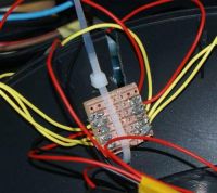 When everything was wired up I had to create a way to connect my Arduino to
everything. It had to be tough, simple to use and preferably safe in the
event of spilled coffee. I ended up with a pair of female header rows poking
through the outer shell.
When everything was wired up I had to create a way to connect my Arduino to
everything. It had to be tough, simple to use and preferably safe in the
event of spilled coffee. I ended up with a pair of female header rows poking
through the outer shell.
This is not entirely ideal. The main problem is that it's a hassle to connect nine jumper wires from a breadboard or Arduino every time I want to use it, as I found out later on. What's more, this is horrible for a more permanent setup as it's bulky and the wiring really gets in the way. If I ever do something like this again, I'll look for a suitable connector with a ribbon cable.
With that finished I had to put everything back together. I didn't really want to: there were a few things I couldn't (reliably) test with the machine opened up. After some more tests and doublechecks I finally did reassemble the machine, and to my surprise everything still worked like a charm!
Getting my Arduino to interact with this safely took a little extra work, and then I still had to write the code to expose convenient functionality like "Make me two cups of coffee". That's (maybe) for another post.
In closing
Some details that are a Good Idea to consider during any such project:
- Before patching into anything, decide aproximately where and how you'll place the outputs. Make sure the wires are long enough for that.
- Don't forget to provide a common ground between the device and your external circuitry, or sensor data might be all over the place.
- Although many of these systems have logic level circuits it may not always be a good idea to join that to the Arduino's Vin - in my case "logic level" turned out to be very noisy.
I really enjoyed this project. It was a first for me, and not only did nothing catch fire, everything still works! If you're interested in details or particular challenges I may have encountered, feel free to ask.